![]()
![]()
![]()
![]()
![]()
Background
Hydroforming is a process which is more widely used in Europe than in the US, although that is changing. The hydroformed part that is most familiar to the average person is probably the tee shaped copper pipe fitting used in most homes, but there are many other applications. Among these are automotive exhaust headers and structural members. The component examined here was made of aluminum and was approximately eight inches or 20 cm long.
The purpose of this work was to examine the ability of the finite element code LS-DYNA to simulate the hydroforming process. By correctly simulating the process, it can be optimized before any tooling is created. Hydroforming tooling is typically very expensive, hundreds of thousands of US dollars or more. By avoiding trials on the physical tooling, expense and development time are significantly reduced. In this case the tooling was already available, but the process parameters had not been determined, much less optimized.
Description
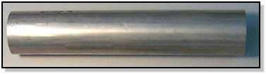
The hydroforming process typically starts with a tube, as shown below.
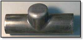
The final shape in this case is shown in the next figure.
The tooling is held in place by a large press, and has an internal shape which matches the final shape of the part. There are movable sections to the tooling that control the part deformation as fluid is pumped into the tube. The part is essentially blown up like a balloon. The figure below illustrates the tool movement.
The backup piston is needed to support the tee dome as it forms and prevent rupture. The figure below shows the initial position of the tube, (a), and the final part, (b).
Simulation Results
There were too many variables in this process to discuss them here, including timing and speed of the piston movements, the pressure-time relationship, tube material and thickness, among others. All of these had to be correctly simulated to achieve valid results.
Shown below is a plot of the end feed forces vs. time. It is important to predict the end feed forces since the manufacturing equipment must be properly sized. The agreement between the simulation and experiment was good.
Another important question that has to be answered is whether the final part will have sufficient thickness for its intended purpose. A structural member must be strong enough to withstand the stresses imposed on it in service. The wall thickness of the experimental part was measured along a line as shown below.
The resulting thickness was compared to the simulation as shown in the next plot. The agreement was good, although the simulation overpredicted the thickness by around 10 percent. Still, the quality of the simulation was more than sufficient to design the manufacturing process.
Finally, simulation can show results which would be too tedious and/or expensive to obtain from actual tests. The figure below shows the thickness over the entire part (blue is thicker while red is thinner.) Such a detailed thickness map would be very time consuming to measure from a physical specimen, but it is useful information. The simulation shows the extent of the thinning in the dome and the thickening near the open ends. The process could have been further optimized to minimize these effects before a part was ever produced.
Move your mouse over the figure below to see an animation of the simulation (requires javascript).
Conclusions
This has been a quick summary of a complex subject. The important points are
that the simulation was shown to be accurate and was actually used to help
set up the process. Building the model was much faster and much
less expensive than attempting to completely develop the process on the
press. In a production environment, this would mean faster, cheaper
development, a better optimized part at the outset, and more confidence in
the tooling design.
|
Copyright © 2000 - 2018 Nonlinear Engineering, LLC |

|
Page last updated 05 July 2018 |